Welcome to Bob & Eileen's web site. Bob generally blogs here while Eileen blogs over at her site. You can see our photos from here or click the little camera in the upper right corner.

Calendar

April 2024
S M T W T F S
 123456
78910111213
14151617181920
21222324252627
282930  

July 20, 2008

AVR32 Prototyping Board
Filed under: Electronics — Bob @ 11:00 am

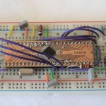
I found an interesting AVR32 development kit online that promised to be very inexpensive yet flexible enough for full prototyping. I quickly jumped at the chance to order one of the AVR32 DIL modules, and after a quick email with Rikard Strömmer (the seller) to work out the details I bought it via Paypal. It arrived in the mail last week and I spent a few hours yesterday playing with it.

Rikard sent me the full development kit, asking for some feedback. I found a few very minor documentation errors (he will fix them pretty soon I expect) but otherwise the kit went together exactly as advertised. I took several pictures during the build, you can see them here.

Anyone who already has a well-stocked prototyping workbench doesn’t really need anything more than the AVR32 DIL module, but even so it was very convienent to have just about everything required included – you have to provide your own 9v battery, some jumper wire and a solderless breadboard.

I’ve just started to play with the software side. Atmel makes a very rich software library with plenty of examples available online. They also supply a version of GCC, similar to the WinAVR package for the 8-bit AVR line. It is nice to see them taking the free software approach, makes it very accessible for hobbyists.

Rikard’s instructions have you modify one of the Atmel examples as your first program. It blinks one of the LEDs and uses the push button (left side of the board) to turn the second LED on. The reset button (right side of the board) works too. I made a little movie of it in action, watch it here.

The AVR32 is quite a bit more powerful than the 8-bit AVR processors I’ve been using in my robot projects. I’m not quite certain what I’m going to do with it yet but it would make a great upgrade for the AVRCAM project, or maybe use it for the heart of an inertial navigation unit, or maybe as the brain for a whole new robot project.

August 26, 2007

GPS over CAN

Filed under: Electronics,Robots — Bob @ 5:36 pm

I’ve put together pictures of the CAN bus “sniffer” project I made recently. Here is a picture of the “sniffer” hardware implementation, connected to another project that reads data from a GPS module (that small square thing in the lower right corner of the photo).

The basic idea is that the GPS interface board (the green board at the bottom of the picture) is reading data from the GPS module, doing some processing of the data, then forwarding latitude and longitude over the CAN bus to anyone who wants to listen. Someday I’m planning to implement a robot that will use that data to help navigate.

My robotics library contains the “sniffer” demo program (it uses the same hardware as the can_mcp2515 demo) as well as the code I wrote to parse the GPGGA-style sentences from a GPS module like this one.

August 21, 2007

What I Did With My Summer Vacation

Filed under: Electronics,Software — Bob @ 8:07 pm

We just returned from ten days away on Salt Spring Island doing not a lot. It was one of those holidays where we didn’t have any plans except to relax, drink some wine, read some books, and enjoy ourselves. Except that I kept myself busy with a couple of electronics projects and my ever-expanding library of robotics-related code.

implementation.jpgI’ve become really interested in using the Controller Area Network technology to have multiple processors communicating together. While researching the options I found this project: CAN-CAN. I liked the simplicity of using the Microchip MCP2515 and it’s less expensive than using one of the Atmel processors with built-in CAN support. And this project really made it easy, I starting thinking it was something I could probably do. So I did! Here is the schematic for my version.

My first project used two separate ATMega8 processors talking to each other over a CAN bus. I read through the source code from the original project but figured I could build my own version, integrated into my own library of code for my robots. I made a number of improvements, making it easier to configure for different hardware. The main program sends a short text string from one processor to the other, where the case is reversed (uppercase to lowercase and vice versa) and a reply is sent back. Here is a picture of what it looks like in action on the screen.

I spent part of my holiday cleaning up the code and implementing interrupt-driven TX and RX. The fun didn’t stop there though. I wrote a second program that “sniffs” the CAN bus and pretty-prints out each message. This has turned out to be very useful while developing other programs with the library (more on this later).

I’ve packaged up my entire library plus these two demonstration programs and made it available for download here. There isn’t a lot of instructions but I’ll probably try to put together something in the future (maybe my next holiday?).

December 5, 2006

Graphical LCD Project

Filed under: Electronics,Robots,Software — Bob @ 10:13 pm

cfax_large.jpgI’ve been playing with the CFAX 128 x 64 pixel graphical LCD from Spark Fun. This is a really nifty graphical display that includes a four-wire resistive touch screen and white backlight. The picture here (click it to see the larger version) has the backlight turned off and you can see it’s still pretty visible.

I decided to write some simple code to draw text and rectangles. The picture shows that stuff pretty well. I also got the touch screen logic working but that isn’t really demonstrated in the picture.

I’ve hooked it up to an AVR Mega 88 on a prototyping board, which gives just barely enough output pins to drive it. I will probably switch to a 40-pin Mega 16 to complete my experiments, as I want to use it with my on-going CAN project; it will require a few more i/o pins that what the 28-pin Mega 88 has available. The idea is to make the LCD available to all CAN nodes in a larger, multi-processor robot suitable for the SRS Robomagellan contest or something similar.

The display has its own memory buffer for the 128 x 64 pixel grid and also has about ten different icons above the top row. It’s pretty simple to interface, and fortunately Spark Fun has some useful sample code here. I also found some sample code from the original manufacturer here.

I also found a nifty article in a recent Circuit Cellar that gave me some inspiration. Look for the issue that covers various video, LCD and LED display projects. My long-term goal is to assemble all of my AVR software into an open source package under the GPL. When I get around to doing it I’ll post it here.

« Previous Page
Powered by: WordPress