Wheels go round and round
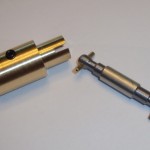
 Today marked quite the milestone for my Outdoor Robot project. The last remaining mechanical parts to make for the drive train functional are complete! In the picture here you can see the brass coupler and a steel drive shaft. The gearbox from the RC truck was originally set up to use a “dogbone” drive shaft – a linkage that allows rotation plus slight shifts up and down without stressing the shaft itself. A real “dogbone” shaft has a ball on each end with a pin to fit into the groove of the receptacle socket. Mine were made on my lathe and aren’t quite as nice, but still functional.
The drive shaft is made from 1/4″ steel rod turned down at each end using my Sherline lathe. This was the first time I turned steel on it, and it was surprisingly easy to work with. So far I’d say brass and steel are better materials to work with than aluminum (at least on the lathe). I turned each end down to 0.2″ then proceeded to cut the end to be somewhat ball-shaped. I only needed a couple of these so eyeballing it worked really well. The pin is some brass rod I had, super-glued into place. I liked the idea of using a softer material so it can shear away if necessary to prevent motor or gearbox damage in case of excessive force.
The coupler has a socket at one end (to accept my faux-dogbone drive shaft) and a 6mm hole with set screw to attach to the motor shaft. I turned some brass stock down to 0.6″ then drilled out the center for the motor shaft. Mounting it on my mill gave me a good setup to drill the hole for the set screw and mill out the groove on the socket. A tapped hole in the side for a 8-32 set screw completes the job. Depending on how well this holds up I may end up making a new version out of steel.
Here is another picture of the coupler and drive shaft, showing how the two parts fit together. The last picture shows the parts mounted on the robot itself. This now means the mechanical part of the drive train is complete, and (with some batteries and electronics) the robot will soon be rolling around my yard.


