Welcome to Bob & Eileen's web site. Bob generally blogs here while Eileen blogs over at her site. You can see our photos from here or click the little camera in the upper right corner.

Calendar

May 2024
S M T W T F S
 1234
567891011
12131415161718
19202122232425
262728293031  

July 4, 2010

Wheels go round and round

Filed under: Machining,Robots — Bob @ 8:02 pm

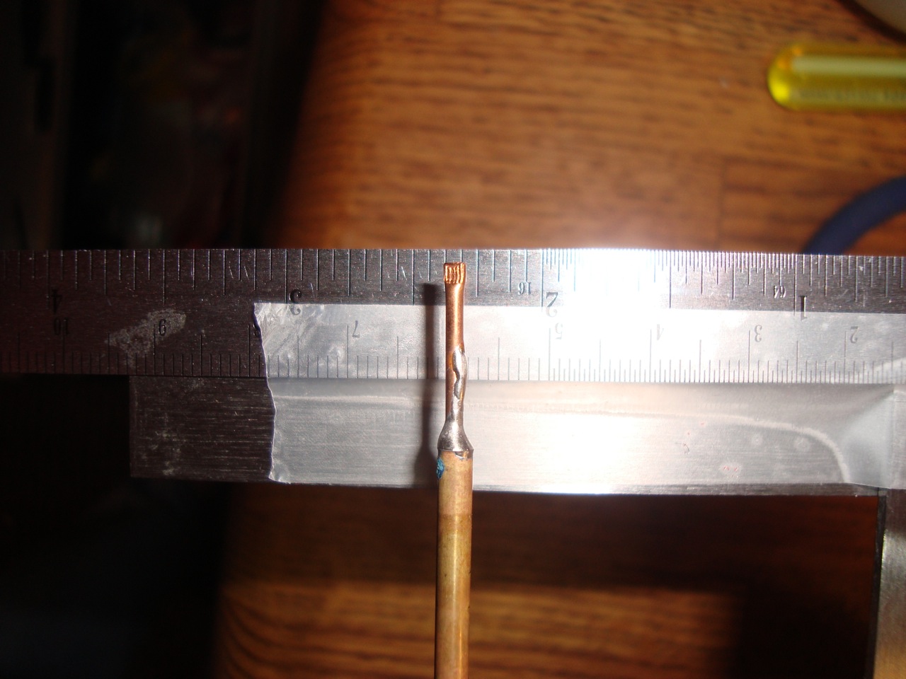
Today marked quite the milestone for my Outdoor Robot project. The last remaining mechanical parts to make for the drive train functional are complete! In the picture here you can see the brass coupler and a steel drive shaft. The gearbox from the RC truck was originally set up to use a “dogbone” drive shaft – a linkage that allows rotation plus slight shifts up and down without stressing the shaft itself. A real “dogbone” shaft has a ball on each end with a pin to fit into the groove of the receptacle socket. Mine were made on my lathe and aren’t quite as nice, but still functional.

The drive shaft is made from 1/4″ steel rod turned down at each end using my Sherline lathe. This was the first time I turned steel on it, and it was surprisingly easy to work with. So far I’d say brass and steel are better materials to work with than aluminum (at least on the lathe). I turned each end down to 0.2″ then proceeded to cut the end to be somewhat ball-shaped. I only needed a couple of these so eyeballing it worked really well. The pin is some brass rod I had, super-glued into place. I liked the idea of using a softer material so it can shear away if necessary to prevent motor or gearbox damage in case of excessive force.

The coupler has a socket at one end (to accept my faux-dogbone drive shaft) and a 6mm hole with set screw to attach to the motor shaft. I turned some brass stock down to 0.6″ then drilled out the center for the motor shaft. Mounting it on my mill gave me a good setup to drill the hole for the set screw and mill out the groove on the socket. A tapped hole in the side for a 8-32 set screw completes the job. Depending on how well this holds up I may end up making a new version out of steel.

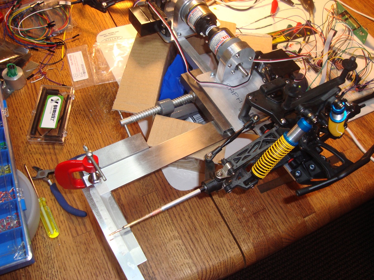
Here is another picture of the coupler and drive shaft, showing how the two parts fit together. The last picture shows the parts mounted on the robot itself. This now means the mechanical part of the drive train is complete, and (with some batteries and electronics) the robot will soon be rolling around my yard.

July 1, 2010

More progress on the Outdoor Robot

Filed under: Machining,Robots — Bob @ 4:00 pm

I’ve made a number of additions to my Outdoor Robot project, including motor mounts and getting the steering set up.

The motor mounts are milled from half-inch aluminum plate, holding two GHM-04 motors plus shaft encoders from Lynxmotion. These motors should be plenty powerful enough and also have a good top speed for this application. It took me a few hours to mill out the two mounts using my CNC Sherline. I need to make some couplings and drive shafts to get the motors connected to the rest of the drive train.

The steering mechanism is from the original RC truck chassis, I just needed to do something about controlling the servos. I set up an ATMega88 that sends the necessary pulse train for servo control. Eventually this chip will communicate with the Overo over CAN, also talk to the the motor controller board I purchased from Pololu, and will have a custom circuit board. For today its only task is to control the steering servos, accepting keyboard input from a serial console.

I needed to calibrate the servo pulse train to the desired positions of the steering mechanism as its installed. Normally servos are a wide range of motion (most go 180 degrees) and accept a pulse train with widths between 1ms and 2ms. These servos do that just fine, except there was no way to know where “center” was in relationship to the wheels. I also wanted to make sure I was getting approximately the same angle on the front and back steering. I created a little jig using some right-angle machinist squares plus clamps plus a ruler. Finding the center position was easy, then I mapped out the servo position required to move the wheel indicator in half-centimeter increments. I ended up with a table of 25 different entries for the front and the back steering servos that give me consistent control. Given the slop in the steering mechanism from this truck chassis, I figured this was good enough.

Here is a little movie of the steering in action. I set up the camera on a tripod then was pressing keys on my laptop that instructed the microprocessor to move the servos to particular locations. I have fully independent control over the front and back steering, and it really looks awesome.

You might also notice in the top right corner of that picture my new Rigol 50Mhz dual channel oscilloscope. Its a nifty piece of equipment, lets me look at signals like the servo pulse train easily. I picked it up from eBay for a reasonable price and so far (having only used it for a day) am very pleased. I recently also bought a Saleae Logic analyzer that I’ve been pretty happy with. I’ve been using it with the “early preview” version of the Mac software. It has bugs but so far none have prevented me from getting the job done. I’d recommend both pieces of test equipment for your own bench.

April 15, 2010

Overo + Controller Area Network

Filed under: Electronics,Robots,Software — Bob @ 7:20 pm

I’ve had a long interest in using Controller Area Network (CAN) to communicate between different components such as sensors or GPS modules or motor controllers. I wasn’t sure if I could do this with the Gumstix Overo board, but I got excited when I found out that Linux kernel version 2.6.33 would be including a driver for the Microchip MCP2515 CAN chip.

This required creating a custom image for the Overo, which meant setting up a build with OpenEmbedded. The Gumstix guys made it sound pretty easy in their instructions, so I set off to make it happen. I started with a virtual machine with Ubuntu 9.10 and set up bitbake and OpenEmbedded as suggested.

I’ve uploaded a tarball of my user.collection directory with overrides for the Overo machine configuration (you could probably ignore that) and for the Linux 2.6.33 recipe to include my configuration and patches to the Overo’s board initialization code for the MCP2515 chip on SPI bus 1 chip select 0.

My working environment for the org.openembedded.dev component uses change d535da0dfe20e965adb49d3acf720e7f9feb58c6. I’m sure by the time you try this there will be newer versions, but I can’t say whether my patches will work or not.

As for the hardware, the Overo uses 1.8v internally but the MCP2515 uses 5v. I used a few SparkFun logic level converter boards to translate voltages. Despite what you might read on their website, DO NOT USE the RX channels as this will send 2.5v into the 1.8v-capable pins on the Overo! Only use the TX channels (they are bidirectional and work at the correct voltage). I needed to translate five pins (SCLK, MISO, MISO, CS, and an interrupt pin) so I used three of the SparkFun boards.

I was able to use the candump program from the socket-can test tools suite to verify correct operation. Awesome!

January 24, 2010

Outdoor Robot Taking Shape

Filed under: Machining,Robots — Bob @ 5:01 pm

Between work, the holidays, and moving to a new house I’ve had little opportunity to work on my Robo-Magellan outdoor robot. That changed yesterday where I spent about five hours machining up two base plates for it. My little Sherline mill doesn’t have the working envelope to do the whole thing in one piece, so I decided to create two plates connected together.

Here is a picture of what each plate looks like after a quick cleanup (with the original base plate from the RC truck included).

Yesterday’s work produced the two plates, including countersunk holes for some mounting points, just like the original. I’m really happy with the progress made so far, but there is much left to do even to get the mechanical stuff done. Next up will be to make the connecting rods that will form the spine, then to make the motor mounts. Lastly I need to create a new top deck that will hold the electronics and sensors.

As for the brain, I opted for a Gumstix Overo Air module with a Tobi carrier board. This seemed to be a good tradeoff for weight, power consumption, and capability. I also bought a motor controller and servo controller from Pololu.

I need to find a good polymer battery to provide power for everything, hook up some sensors, write some software, etc. but I’m really happy with the progress this weekend.

October 31, 2009

Future Robo-Magellan Robot

Filed under: Robots — Bob @ 7:06 pm

robomagellan chassisI’ve finally gotten some real traction on my Robo-Magellan robot. The picture here shows the chassis I purchased from eBay for a platform to get started.

Actually I bought two of them, as I really want to have independent steering in the front and back. My plan was to chop the chassis in half, simply “glueing” one front end to the other front end. Now that I’ve had a look at how its put together I’ve got a slightly different plan, to make better use of the way the motor is connected. I can combine the back transmission and motor mount with the front axle pretty easily, without loosing much flexibility. It looks like I’ll be able to get independent four-wheel steering out of it too. I need to machine a new base plate, but I was pretty much expecting to do that anyways.

The next thing to do is select a “brain”. I’ve got plenty of sensors and motor controllers, but nothing that will give me a “real” platform for software development. The AVR processors are simply too underpowered for this sort of job, and the Tin Can Tools Hammer board I’ve been playing with recently doesn’t have enough I/O. I really want something that can run Linux, preferably also run Python for the main program. I could write it all in C++ but the development time can be reduced by using Python.

Anyone else building a Robo-Magellan robot?

« Previous PageNext Page »
Powered by: WordPress