Welcome to Bob & Eileen's web site. Bob generally blogs here while Eileen blogs over at her site. You can see our photos from here or click the little camera in the upper right corner.

Calendar

April 2024
S M T W T F S
 123456
78910111213
14151617181920
21222324252627
282930  

July 1, 2010

More progress on the Outdoor Robot

Filed under: Machining,Robots — Bob @ 4:00 pm

I’ve made a number of additions to my Outdoor Robot project, including motor mounts and getting the steering set up.

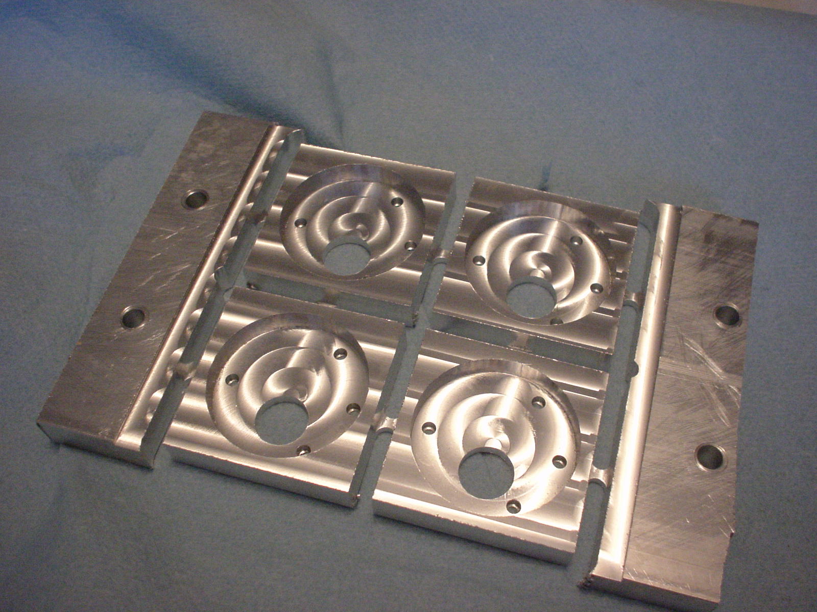
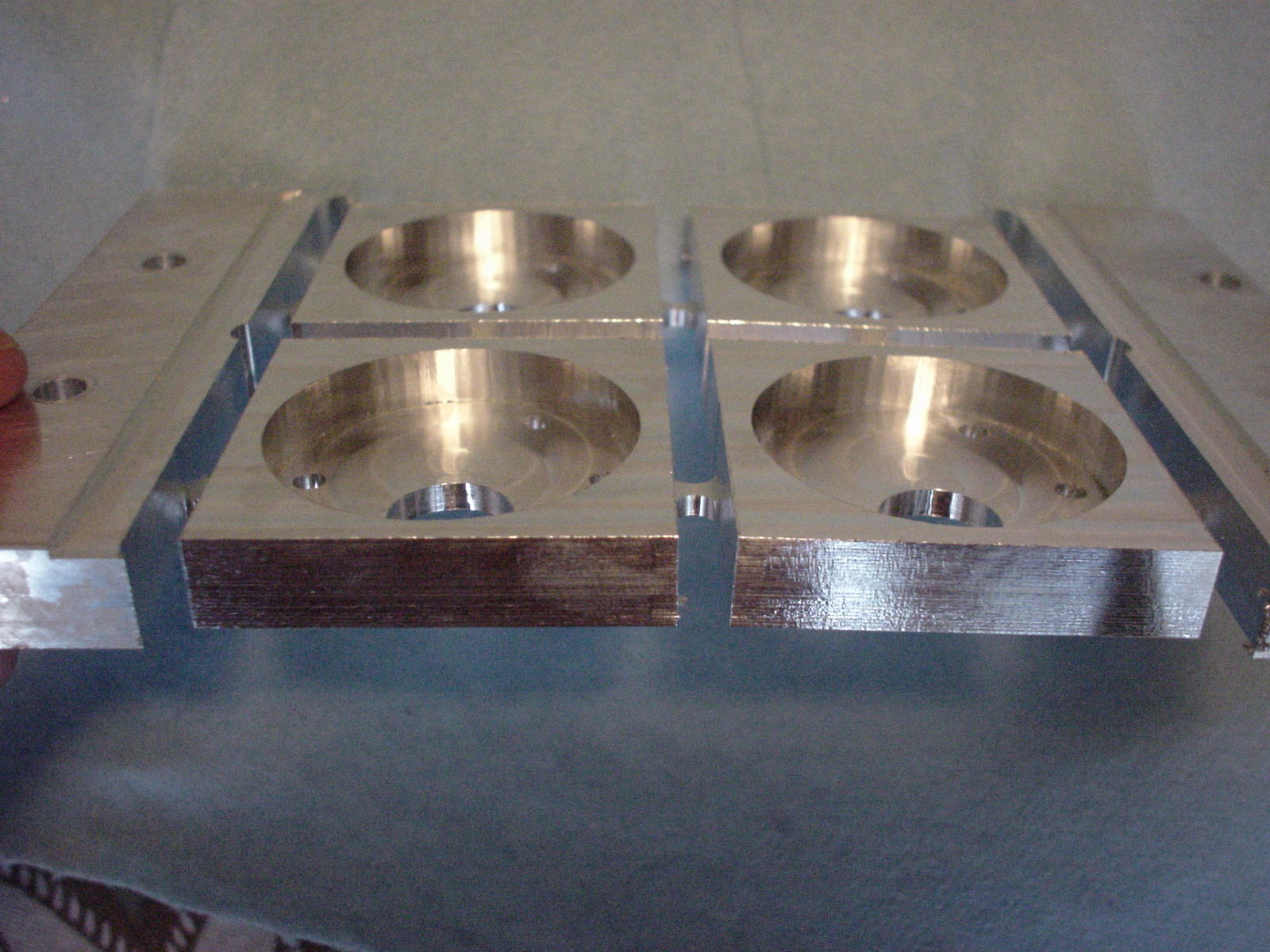
The motor mounts are milled from half-inch aluminum plate, holding two GHM-04 motors plus shaft encoders from Lynxmotion. These motors should be plenty powerful enough and also have a good top speed for this application. It took me a few hours to mill out the two mounts using my CNC Sherline. I need to make some couplings and drive shafts to get the motors connected to the rest of the drive train.

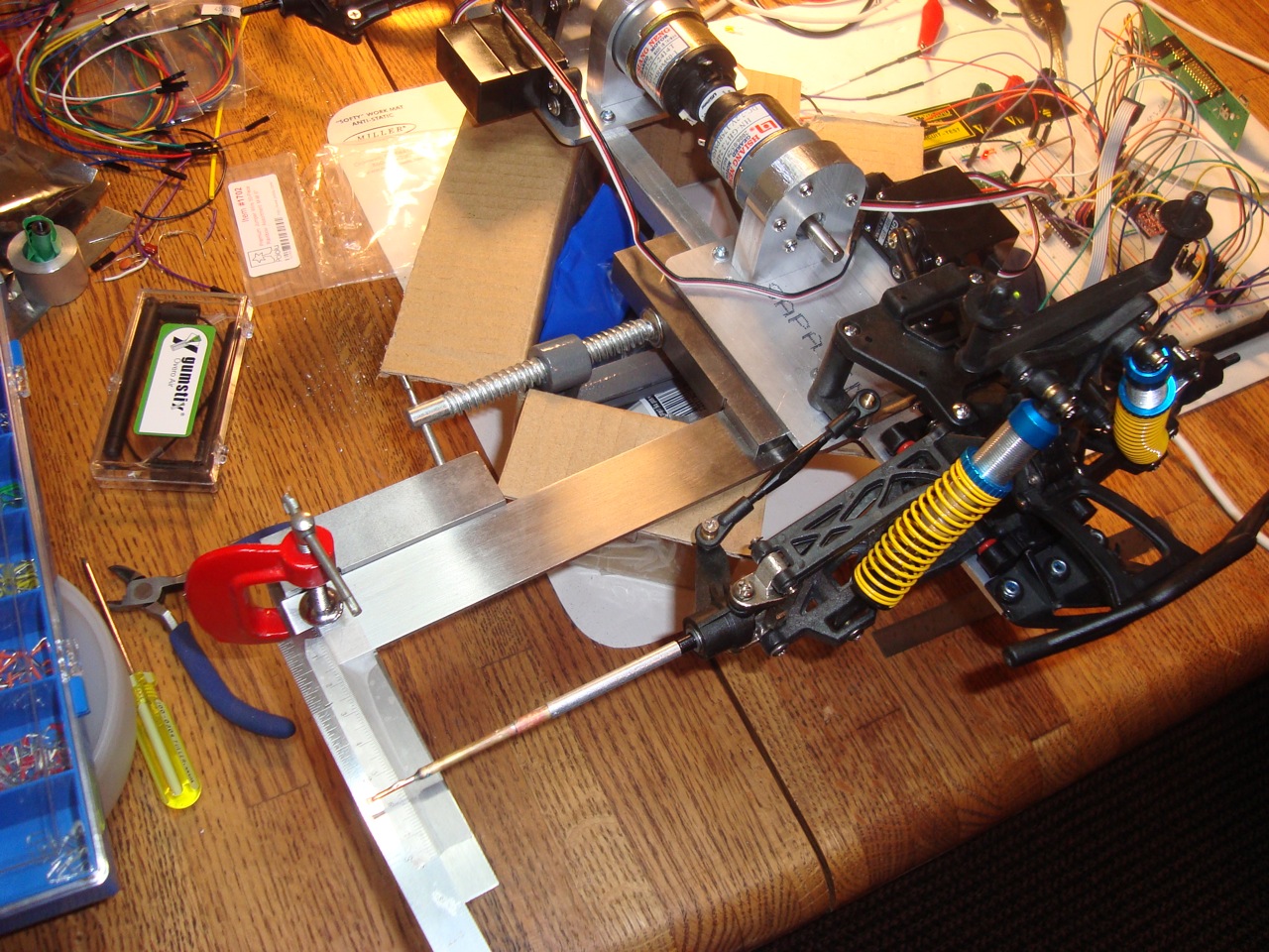
The steering mechanism is from the original RC truck chassis, I just needed to do something about controlling the servos. I set up an ATMega88 that sends the necessary pulse train for servo control. Eventually this chip will communicate with the Overo over CAN, also talk to the the motor controller board I purchased from Pololu, and will have a custom circuit board. For today its only task is to control the steering servos, accepting keyboard input from a serial console.

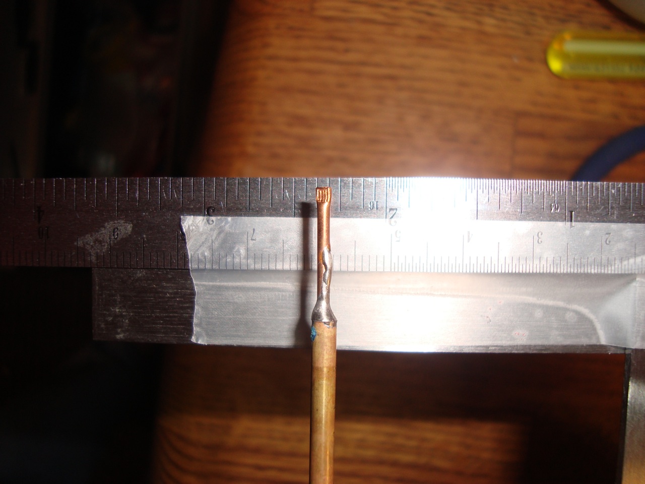
I needed to calibrate the servo pulse train to the desired positions of the steering mechanism as its installed. Normally servos are a wide range of motion (most go 180 degrees) and accept a pulse train with widths between 1ms and 2ms. These servos do that just fine, except there was no way to know where “center” was in relationship to the wheels. I also wanted to make sure I was getting approximately the same angle on the front and back steering. I created a little jig using some right-angle machinist squares plus clamps plus a ruler. Finding the center position was easy, then I mapped out the servo position required to move the wheel indicator in half-centimeter increments. I ended up with a table of 25 different entries for the front and the back steering servos that give me consistent control. Given the slop in the steering mechanism from this truck chassis, I figured this was good enough.

Here is a little movie of the steering in action. I set up the camera on a tripod then was pressing keys on my laptop that instructed the microprocessor to move the servos to particular locations. I have fully independent control over the front and back steering, and it really looks awesome.

You might also notice in the top right corner of that picture my new Rigol 50Mhz dual channel oscilloscope. Its a nifty piece of equipment, lets me look at signals like the servo pulse train easily. I picked it up from eBay for a reasonable price and so far (having only used it for a day) am very pleased. I recently also bought a Saleae Logic analyzer that I’ve been pretty happy with. I’ve been using it with the “early preview” version of the Mac software. It has bugs but so far none have prevented me from getting the job done. I’d recommend both pieces of test equipment for your own bench.

January 24, 2010

Outdoor Robot Taking Shape

Filed under: Machining,Robots — Bob @ 5:01 pm

Between work, the holidays, and moving to a new house I’ve had little opportunity to work on my Robo-Magellan outdoor robot. That changed yesterday where I spent about five hours machining up two base plates for it. My little Sherline mill doesn’t have the working envelope to do the whole thing in one piece, so I decided to create two plates connected together.

Here is a picture of what each plate looks like after a quick cleanup (with the original base plate from the RC truck included).

Yesterday’s work produced the two plates, including countersunk holes for some mounting points, just like the original. I’m really happy with the progress made so far, but there is much left to do even to get the mechanical stuff done. Next up will be to make the connecting rods that will form the spine, then to make the motor mounts. Lastly I need to create a new top deck that will hold the electronics and sensors.

As for the brain, I opted for a Gumstix Overo Air module with a Tobi carrier board. This seemed to be a good tradeoff for weight, power consumption, and capability. I also bought a motor controller and servo controller from Pololu.

I need to find a good polymer battery to provide power for everything, hook up some sensors, write some software, etc. but I’m really happy with the progress this weekend.

August 9, 2009

Vancouver Robotics Club

Filed under: Machining,Robots — Bob @ 1:36 pm

Today was the monthly meeting of the Vancouver Robotics Club. There were some really cool projects to see. I took my Tin Can Tools Hammer project along to show everyone what I’ve been working on. Most recently I’ve been connecting it up to a touch screen using I2C. When its done I’ll post more about it.

4-legged walkerJames brought a beautiful four-legged walking robot project. Its still a work in progress but as you can see from the photos it is very well crafted. Here is a movie of it walking. James describes it as “swimming”. He wants to redesign it to add another servo to the lower leg to enable more precise movements and better walking. I’m sure it will be amazing.

Ian brought his hacked Roomba to show off, here is a movie of it wandering around the floor. At about the 6 second mark you can see him driving it from his tablet computer; his Rooma has a Bluetooth link, and he wrote some custom software to drive it around. Later in the same video (around the 10 second mark) you can see my Metal Insect robot wandering into the frame. For a while Ian was “herding” it around the room!

By the way all of the video was taken with my iPhone 3GS then resampled in QuickTime Pro to be a reasonable size download. Neat!

August 26, 2008

Motor mount, in aluminum

Filed under: Machining,Robots — Bob @ 8:32 pm

I have been working, ever so slowly, on a larger wheeled robot. My efforts to date have mostly comprised of collecting parts: motors, wheels, gears, a GPS module, various electronics bits, a nifty digital compass, etc. I’ve finally started design and manufacture of various parts to start stitching together everything.

My first machined part is a bracket to mount the motor (a Lynxmotion model). This picture shows the four brackets I need; one is mounted on a motor, the one in the front-left is finished and the other two need only to have the “tabs” cleaned up.

I designed the part using Inkscape then exported a DXF file and did the machining on my CNC-equipped Sherline (as described in a previous post). You can see the image of the Inkscape design here. This process works quite well for me.

The problem of course is that the design requires “tabs” between the parts in order to be able to hold the whole thing together while machining. I’ve captured a couple of photos here and here to show what it looked like before I cut everything apart.

Next up is the brackets to attach to these mounts. My initial design will take longer to machine though. The idea is to allow each wheel to pivot independently; the bracket is an “L” shape that extends up and over the center of each wheel. It will make more sense when I have some pictures.

April 19, 2008

More on Inkscape + DXF

Filed under: Machining,Software — Bob @ 9:16 am

I wrote a few days ago about my work on a better DXF export module for Inkscape. I was using it again today for my upcoming CNC milling efforts and found a few bugs plus added another feature.

There is a bug in Inkscape’s simpletransform.py when it attempts to handle transformations of scale, rotate, etc.

I also improved my own exporter and added a feature that creates POINT entities instead of LINE entities for objects on layers that end in the word “drill”. SheetCam uses POINT objects for drilling and I didn’t have an easy way to create them. There really isn’t a way to turn this behavior off (other than not end your layer names with “drill” so if you end up using this extension, be aware of this). It works best with small rectangles because it will compute the center point of the path bounding box as the location for the POINT. I just create small rectangles the same size as my drill hole.

I also corrected the list of dependencies in the better_dxf_output.inx file.

For anyone who is interested, visit this page to download all of the required files.

« Previous PageNext Page »
Powered by: WordPress